


One Aviation Platform for Pilot Logbook, Mock Exam and Career Progression
Prepare with New Zealand aviation mock exams, manage your pilot logbook, track training, experience, compliance and generate reports, CVs, and future job-ready evidence.

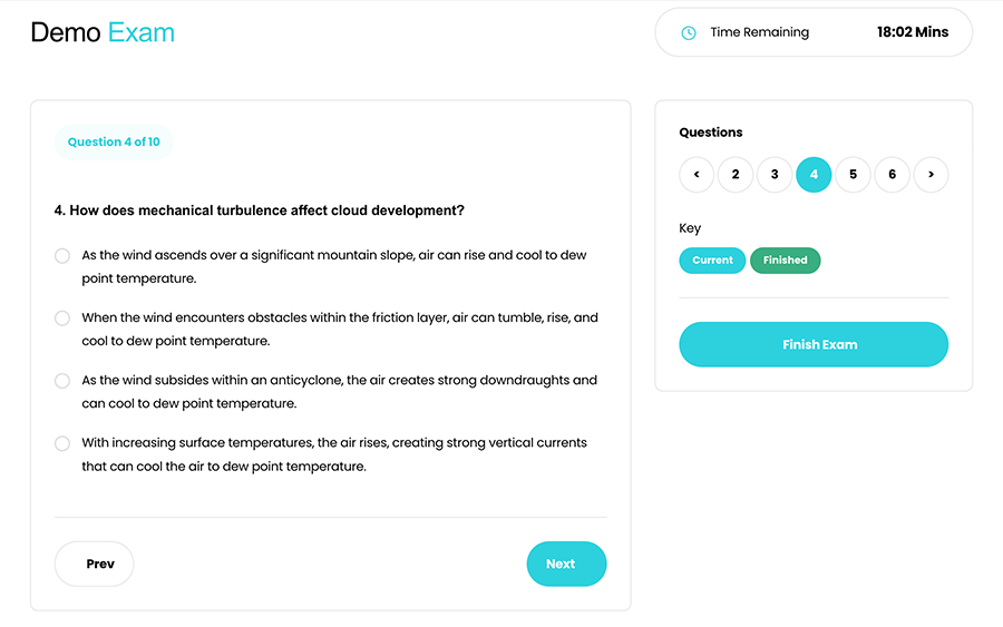
Mock Exams with Unlimited Access & Realistic Results
- Unlimited Access To All Exams
- Authentic Exam Conditions with Timers
- Detailed Results & KDR Reports
- Smarter, Targeted Learning
 Trusted by Pilot Students Nationwide
Get Started With Subscriptions

Create Your Account


Buy a Subscription
Select either a monthly or six-month subscription. Both plans grant you unlimited access to all 30 versions of the PPL/CPL mock exams (covering 1000+ questions) throughout the subscription period.

Start Your Mock Exam
Once your subscription is active, you can begin any of the available mock exams. Each exam simulates real ASPEQ test conditions, so there’s no pause button, helping you get used to the pressure.

Get Instant Results
Once you finish your exam, the system automatically generates your results. For each passed exam, you'll see which questions you answered incorrectly, along with the correct answers and related syllabus items.


NZAviator App built for Kiwi pilots to accurately log flights, track progress, and turn real experience into meaningful career opportunities when it matters most.
Digital Pilot Logbook
Professional CAA NZ-aligned digital pilot logbook built for Kiwi pilots. Say goodbye to messy Excel spreadsheets logbooks, and expensive subscriptions. NZAviator APP automatically totals your flight hours, tracks currency and expiry dates, and generates reports and logbook exports — giving you a secure, modern electronic logbook in one place.
| DATE | AIRCRAFT | CREW | DETAILS OF FLIGHT | SINGLE-ENGINE | MULTI-ENGINE | INSTRUMENT | TAKE-OFFS & LANDINGS | DUTY | TOTAL FLIGHT TIME |
|||||||||||||||||||||||
|---|---|---|---|---|---|---|---|---|---|---|---|---|---|---|---|---|---|---|---|---|---|---|---|---|---|---|---|---|---|---|---|---|
| TYPE | REG'N | ENGINE TYPE | PILOT IN COMMAND | CO-PILOT OR STUDENT | DAY | NIGHT | DAY | NIGHT | FLIGHT | GROUND | NON-PREC. APP. | PREC. APP. | TAKE-OFFS | LANDINGS | TIME ON | TIME OFF | TOTAL DUTY | |||||||||||||||
| DUAL | PIC | DUAL | PIC | DUAL | PIC | CO-PILOT | COMM'D PRACTICE |
DUAL | PIC | CO-PILOT | COMM'D PRACTICE |
ACTUAL | SIMULATED | DAY | NIGHT | DAY | NIGHT | |||||||||||||||
| 18/12/2025 | C172 | ZK-TAN | PISTON ENGINE | SELF | T GILLAN | Medium Turn | 1.1 | 2 | 2 | 1.1 | ||||||||||||||||||||||

Turn Flight Data Into Trusted
Career-Ready Proof
A clean, New Zealand-focused web application with no subscription—built to help you log and organise flights, track training and currency, and access powerful reporting across all devices whenever you need your data.

NZ-Ready Data Matching
Structured fields map your flight time, landings, and categories correctly—no messy spreadsheets.

Fast Logging & CSV Import
Add flights faster with smart inputs, default settings, and CSV import for clean, consistent NZ logbook formatting.

Clean Reports & Exports
Generate totals and breakdowns (PIC, Dual, Night, Instrument) for training, employers, and audits.

User-Friendly Interface
A modern, clean layout that’s easy to use on any device—less clicking, more flying.

Secure by Design
Your logbook stays private with secure sign-in and permission-based sharing controls.

24/7 Support
Quick help from people who understand NZ pilot training, CAA requirements, and real workflows.